Can’t find your discipline or profession? Write to us and we’ll
do our best to work something out.
Every project is unique.
We adjust our services to your needs.
LLRF system has a key role in the overall performance of a particle accelerator since it is responsible for the accurate control of electromagnetic field amplitude and phase inside the accelerating structures. It has therefore a crucial impact on beam quality. Instrumentation Technologies provides state-of-the-art LLRF solutions tailored on customer needs.
Benefits:
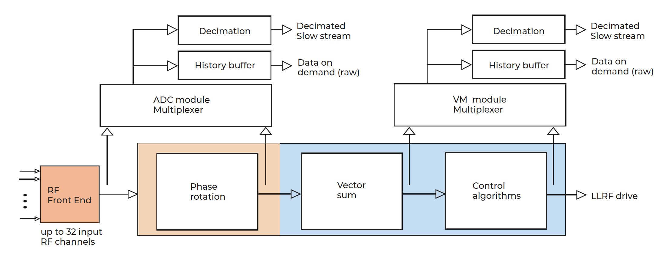
Data processing:
Libera LLRF, the industrial digital RF stabilization system, offers a unique combination of hardware, real-time digital signal processing and software. The system continuously tracks the RF system signals and applies a feedback RF signals to it.
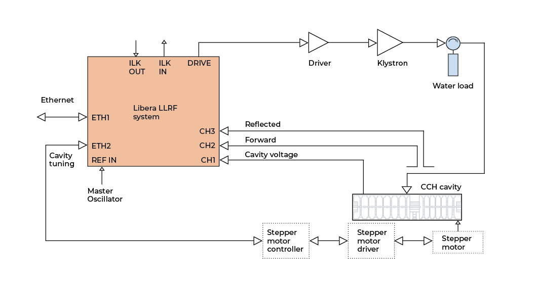
In the figure below, a possible configuration of Libera LLRF is presented. Libera LLRF tracks the cavity voltage (probe) signal and according to it applies a control drive signal to the cavity through the RF system power amplifiers. Further diagnostics on directional coupler forward and reflected signals enable Libera LLRF to measure cavity resonant frequency and therefore act on the cavity tuning system through stepper-motors or other equivalent tuning devices.
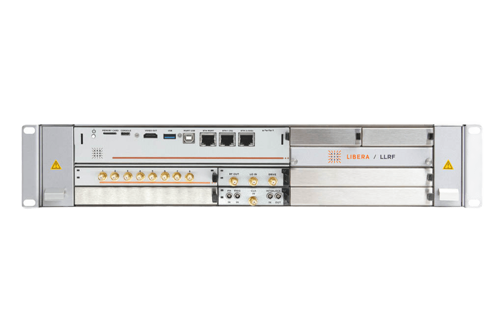
Libera LLRF front and back panel:
Libera LLRF Digital signal processing:
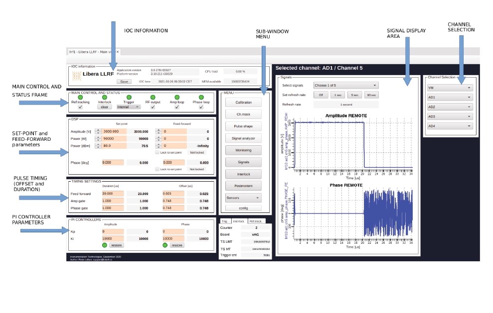
Some Libera LLRF features:
Interfaces:
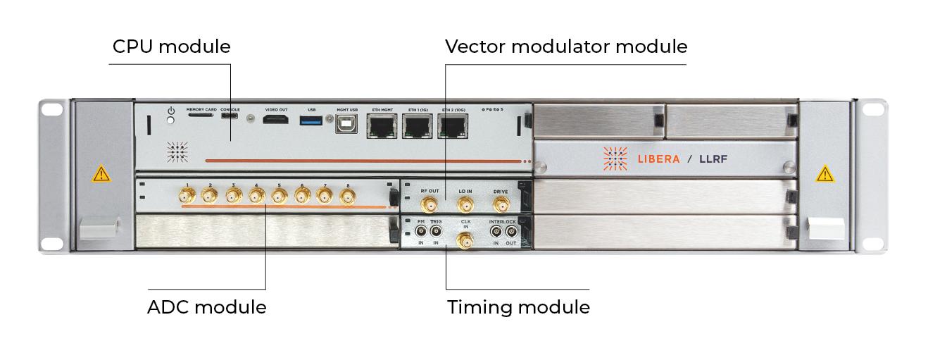
Implements functions of the µTCA Carrier Hub (MCH) with interfaces: 2x PCIe, 2x LXI, JTAG, RS-232, DVI, management USB, management ETH, USB and 2x ETH. A fast PCIe bus is used for the data transfer between COM Express module and AMC application boards. This solution supports the implementation of low-latency control algorithms, real-time data processing and dedicated RF system diagnostics tools.
Double width mid-size AMC modules can process up to 8 RF inputs. The Libera LLRF system is configurable and can host from one to maximum four such modules. A Libera LLRF receiver module includes a calibration system and a LO distribution. The FPGA mounted on the board is used for hardware control and digital signal processing.
Single width mid-size AMC module with two RF inputs and two RF outputs. The two inputs can be used in feedback. One of the two RF outputs is used for the drive signal generation. The FPGA mounted on the board is used for hardware control and digital signal processing.
Single width mid-size AMC module. Generates a low jitter local oscillator (LO) signal and a suitable sampling clock for the down-conversion and acquisition processes.
Provide the possibility to add additional features to the Libera LLRF system.
The Libera LLRF system architecture is based on PCIe implemented on AMC standards. It is a user-friendly network-attached device that has a powerful computational interconnect board (ICB) managing a number of satellite boards.
This product runs on Libera BASE.
Learn more about it by clicking here.
![]()
| General product code | LLRF |
| RF input channels | Up to 24/32 channels (6/8 channels per ADC module) |
| RF input frequency | Up to 12 GHz |
| Maximum RF power input | +20 dBm |
| A/D conversion | 130 MSps/250 MSps (16 bits) |
| FPGA processing | Xilinx Kintex Ultrascale |
| RF output channels | 2 (1 RF drive, 1 auxiliary) |
| Maximum RF drive output power | +10 dBm |
| Cooling | Active (Forced Air) |
| Power supply | 110/220 V |
| Dimensions | Libera LLRF processing unit: H: 2 U, W:19" (rack mountable), D: 310 mm. Libera TSRF: H: 2U, W:19" (rack mountable), D: 456 mm |
| Supported modes of operation | Pulsed Continuous Wave (CW) |
| Feedback and control | Intra-Pulse and Pulse-by-pulse feedback, Beam loading compensation, Power amplifier non-linear response compensation |
| Cavity tuning | Directional coupler based detuning calculation, and cavity field decay analysis. Slow tuning PID controller and different stepper-motor interfaces support |
| Machine protection | Low-latency interlock interface (Input and Output) with failsafe logic |
| Temperature stabilization | Temperature stabilized RF front-end option |
| Amplitude stability | < 0.01° RMS* |
| Phase stability | < 0.01° RMS* |
| Latency (Input to Drive output) | Down to 250 ns |
| Long-term temperature stability with temperature stabilized RF front-end | < 100 fs RMS / 72 hours |
*Pulse-by-pulse performance
Request the Libera documentation by filling the form below. We will reply to you shortly.
Libera LLRF is used at the following labs:
Can’t find your discipline or profession? Write to us and we’ll
do our best to work something out.
We adjust our services to your needs.